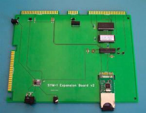
If you have one of the SYM-1 Expansion Boards I’ve made, here’s some useful information I’ve gathered for it.
The Getting Started guide is here.
Here’s a demo video:
The EEPROM on the expansion board is an AT28C256. It contains the SYM-1 monitor, version 1.1, SYM-1 BASIC 1.1, the Resident Assembler and Editor (RAE), and a disk operating system. Binary images of the individual programs and the entire EEPROM are here.
The Disk Operating System’s manual is here. I learned about this DOS from here.
The solid state storage is based on the SD2IEC project, which emulates a Commodore 1541 floppy drive. The SD2IEC project is here. I bought the hardware from here.
SYM-1 manuals and other information are here.
My cheat sheet for using the SYM-1 firmware is here.
The Star Trek BASIC game and a BASIC program to print a picture of Snoopy are here.
I designed laser-cut panels to use as a back and a cover to the SYM-1. You can see them in my original article. The SVG files for making them are here. The shapes are in a template that Ponoko.com, a laser-cutting service, used a few years ago, and they can probably still use them. I made the front and back in clear acrylic, and the LED cover in translucent red acrylic. I then superglued the LED cover into the opening in the front cover. If you decide to make these panels, you’ll need additional bolts and spacers to mount them. I used M3 size bolts, but 4-40 would work too. (By the way, it you look at the SVG files in an editor, you might initially think there are no defined shapes. They’re there; it’s just that the lines are really thin and you need to zoom in to see them.)
You’ll also notice in my video that I have the SYM-1 propped up. I’m just sitting it on a tablet stand. I bought this one from Amazon.
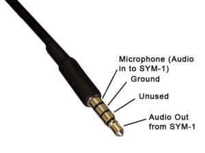
There’s an audio in/out jack that the SYM-1 uses to read and save programs to cassette tapes. However, I have not been able to get it working. I don’t know if the problem is in my board or in my SYM-1. If you want to try it, the audio plug should be wired according to this diagram: