
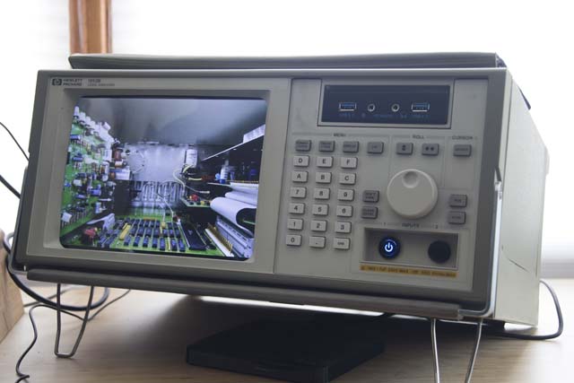
 This is not a Hewlett-Packard logic analyzer. It’s a Core i5 Windows PC.
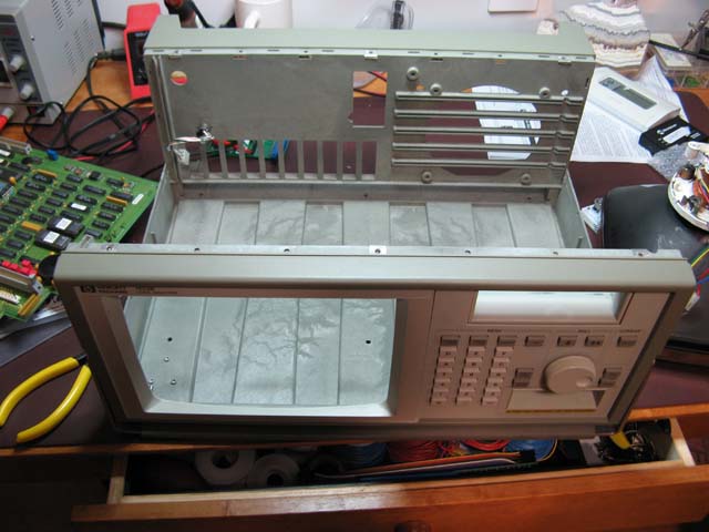
Back in 2010, I built a miniature replica Altair 8800 case for my PC. It’s still running but I needed another desktop PC, and I wanted it to reflect my love for retro electronics. So I bought a non-working Hewlett-Packard logic analyzer on eBay and set about turning it into a mini-ITX PC case.
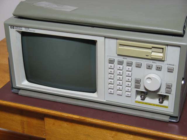
 The logic analyzer had a CRT display, a floppy disk drive, a keypad with buttons and a rotary knob, and BNC connectors for the built-in oscilloscope. I didn’t want to drive the CRT – that would’ve been a real hassle – and it wouldn’t look good if it was dark, so it had to go. The floppy disk would’ve been useless, but the opening could be repurposed. The keypad, of course, had to be able to talk to the PC. And the BNC connectors could be replaced with power and reset buttons.
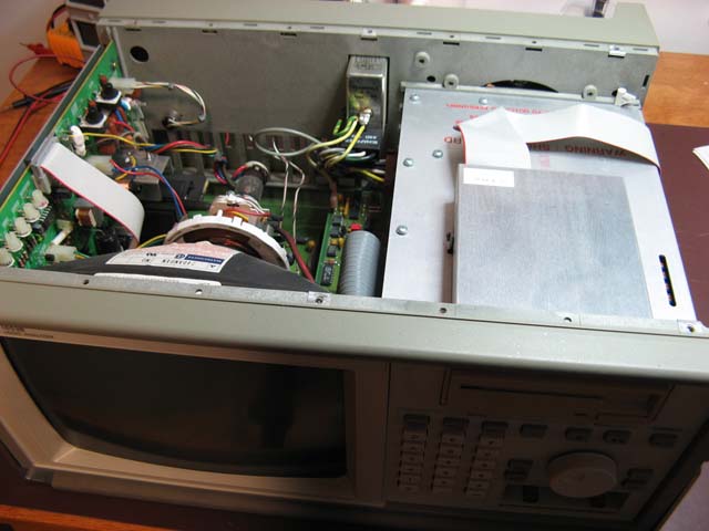
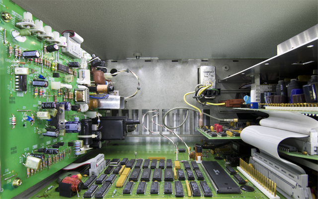
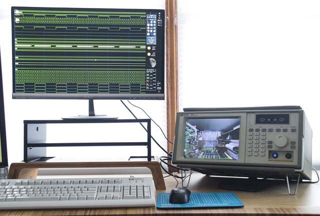
I removed the CRT but before I tore out the rest of the guts, I took a photograph of the inside. My idea was to replace the CRT with an LCD display and set its wallpaper to the picture of the inside of the logic analyzer. This is to give the illusion that you’re looking through a window into the logic analyzer and seeing all that beautiful 1980s technology inside.
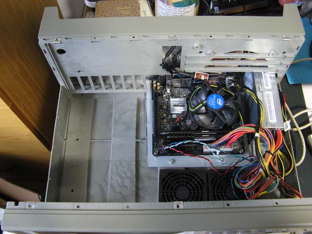
(Actually, replacing the CRT with an LCD was not my first choice. I experimented with having a rear-projection screen and a tiny, short-throw projector at the back of the case. The projector was not able to make a bright image on the rear view screen, even if the room was dark; it was hopeless in a normally lit room. I also considered leaving the retro electronics in the case, mounting a clear window in the bezel, and lighting the interior. But I had to remove at least some of the electronics to make way for the PC motherboard, and a mix of 1989 and 2017 technology would not have looked good.)
I softened an acrylic sheet in the oven, stretched it over the front of the CRT to get its profile, and mounted it in the logic analyzer’s bezel. I bought a 10” LCD display, put it behind the acrylic sheet, connected it to the PC motherboard, and set its wallpaper to the photo of the logic analyzer’s guts. To complete the logic analyzer theme, I set the wallpaper on my primary display to be a logic trace pattern.
The built-in LCD could, of course, be used as the main display for the PC. You could even treat this PC as a modern version of the Osborne 1: just slip a keyboard into the pouch, grab the handle, and you have a modern luggable computer. But while a 5 inch screen was acceptable in 1981, I’m too jaded to work on a 10” screen today. So instead, I just put gadgets on the built-in LCD to display things like a hit counter for my web site (yes, the Microsoft Gadgets from Windows Vista – they can be made to work with Windows 10).
The floppy drive opening was a no-brainer: I filled it with USB and audio ports.
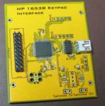 To make the keypad functional, I designed a simple microcontroller-based board that scans the buttons and sends codes to the PC through the motherboard’s USB connector. On the PC, I wrote a program that would read the codes, look up a matching command in a configuration file, and execute it. So now, I can launch programs by pushing buttons on the keypad or adjust the PC’s volume by turning the rotary knob.
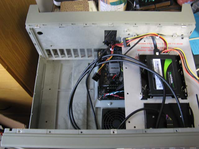
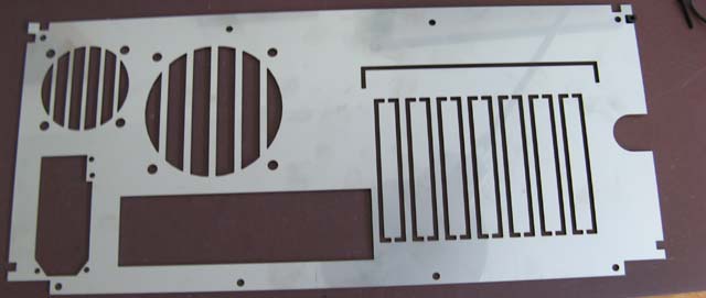
I designed the back panel, where the motherboard ports and power supply are mounted, in OpenSCAD and sent the 2D CAD file off to be laser-cut.
When I was a kid, computers were geeky. At least in my office, they still are!
Love it! A quality case for a quality project.
I helped introduce the 1653A while I was at HP. Brought back some memories.