
 One way of debugging microcontroller-based projects is to send messages out the UART serial port. Then, a UART-to-USB interface can feed the messages into your PC for display. But I wanted a small, portable device for viewing serial data without a PC, and I wanted it to use my cell phone or tablet for its display.
There are a few advantages to this. First, I don’t always have my PC nearby; maybe the project worked fine on my workbench, but doesn’t work “in the field” where I don’t have a PC handy. Second, the UART-to-USB interface sometimes hangs, especially if there are glitches from the system under test (SUT). Finally, sometimes I just don’t want to string the wires from the embedded system to my PC.
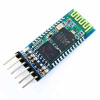
Bluetooth serial transceivers like the HC-05 are cheap on eBay. It would be easy to connect one to an embedded system, but it doesn’t do everything I want:
- I want to be able to change the baud rate that I’m using to listen to the SUT. The HC-05’s baud rate can only be changed by the microcontroller it’s wired to, and it’s a complicated process (toggle a pin, send a command, then reset the HC-05, which breaks any Bluetooth connection that’s been established). The typical SUT is not set up to control an HC-05.
- I want to auto-detect what the baud rate is, and display it. I’ve had bugs caused by the baud rate being set wrong – maybe the microcontroller’s oscillator was not what I thought it was – and auto-detecting the baud rate would troubleshoot that quickly. Also, I simply might not remember what baud rate the SUT is using.
- I want to be able to see whether data is coming from the SUT. When no debugging messages are coming out of an embedded system, it’s hard to know whether the problem is at the transmitting unit, or the receiving unit, or if the SUT just isn’t sending anything. With a mechanism as complicated as a Bluetooth transmitter and a tablet receiver, I wanted an indication right at the SUT of whether data is being sent.
So I decided to make a device that includes the HC-05, a microcontroller (a Microchip PIC32, which is overkill for this project, but it’s one of my preferred devices and it has two UARTs – one for the SUT and one for the HC-05), an LED display, a battery, and a button. Since the C function typically used for printing debug messages is printf and since I’m using Bluetooth, I decided to call the project Blueprintf. I made a logo that looks like the letter f printed on a blueprint of Blueprintf’s schematic.
 Blueprintf connects to the system under test with just two wires: ground and UART Receive (Rx) (connected to the SUT’s UART Transmit (Tx)). Optionally, if I want to send data from my tablet to the SUT, I can connect Blueprintf‘s UART Tx to the SUT’s UART Rx. Blueprintf has its own 9V battery, so it doesn’t need to be connected to the SUT’s power supply.
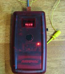
Since Blueprintf is battery powered, I gave it a true on/off switch. When Blueprintf is turned on, it displays the baud rate it is set to, which it remembers from the last time it was on. The display shows four digits, so low baud rates like 1200 and 9600 are shown just like that, whereas faster rates like 19,200 or 115,200 are shown as “19.2” or “115.2”. The display turns off after three seconds. Pressing the button once re-displays the current baud rate; pressing it again advances through the commonly used rates (1200, 2400, 4800, 9600, etc.).
One of the options the button offers is “Auto”. When this is set, Blueprintf waits for data to come from the SUT, finds the shortest pulse, and calculates the baud rate from that. PIC32 UARTs have a baud rate auto-detect feature, but it requires the incoming data to be an ASCII ‘U’ (which in binary is 01010101). My auto-detect does not require that, although it does require that somewhere in the serial data, there is a 010 pattern or a 101 pattern. It watches 25 changes in the signal, so any normal text stream should suffice. Once the baud rate is auto-detected, it is displayed on the LEDs.
On the cell phone/tablet side, I use either BlueTerm+ or SENA BTerm, both available in the Google Play store for Android devices. Other Bluetooth serial apps should work, including iOS apps in the Apple app store.
Bluetooth serial apps can send as well as receive, so text I type at the keyboard gets sent through Blueprintf to the system under test. This allows me to send commands to a microcontroller project (assuming it’s designed to accept them).
Of course, I used my other site, PCBShopper.com, to find the PCB manufacturer with the best balance of low price and fast delivery.
Since I was using the PIC32, I decided to try Microchip’s new Harmony framework. As it turns out, it’s pretty good, and I plan to use it again. It’s been criticized harshly in the Microchip forums for being buggy and incomplete. I had tried their beta version and their 1.00, and I quickly gave up on both of them. But 1.01 is quite usable. There are still modules that are marked as beta, there are still bugs (I reported a few to Microchip myself), and there are features that would be nice to add. But I really like where they’re going with the architecture, and it makes it so easy to use peripherals and timers that I found myself using more features of the PIC32 and writing better code. For example, Harmony provides a timer service that lets you easily request periodic or one-shot callbacks for different spans of time. With this, I eliminated delay loops from my code and made everything work asynchronously. Also, since it was so easy to set up, I used the PIC32’s Input Capture peripheral for my autobaud code – something I had never used before. Input Capture provides high-resolution, accurate timestamps for events like rising or falling edges on input pins. I also liked how, with the click of a checkbox, I could switch between interrupt-driven and polled peripherals, with Harmony generating the interrupt handler or the polling code.
Harmony has intriguing features that I haven’t had a chance to try yet. With the click of a check box, Harmony lets you add a Real Time Operating System (FreeRTOS, or a choice of a few others) to your project, and Harmony integrates with the RTOS automatically. Harmony offers message queues and a command console, both of which are also added to your project with a few clicks.
You can download my source code, schematic, and board design here. The source code uses MPLAB X and Microchip Harmony. The hardware was designed in the free version of DipTrace.

Perfect project !
Why you not use cheapest 8-32 pin MCU ?
And pcb can smaller (as battery size).
I needed an MCU with two UARTs, so that disqualified all Microchip PICs with fewer than 20 pins. The UART Rx pin had to be 5V tolerant, since I might be connecting it to 5V systems, so that narrowed my choices further. Cost wasn’t an issue because (1) the MCU’s price is $4 and I’m only making one of these and (2) I didn’t even pay that much because of Microchip’s generous free sample program.
As for size, I selected the enclosure I wanted to use and made the PCB big enough to position the button and LEDs where I wanted them. So it was for aesthetic reasons only.